Your data center needs 120V single-phase power, but the utility feed is three-wire. A step-down transformer will work— it will also cost you more and take longer to source. There's a smarter path.
Neutral Grounding Transformers (NGTs) convert three-wire distribution systems into four-wire systems at a fraction of the size and cost of conventional step-down alternatives. But specifying one incorrectly can compromise fault protection, voltage regulation, and system safety.
This white paper from the engineering team at Quality Transformer & Electronics (QT&E) breaks down the critical specification inputs — maximum neutral current, fault current withstand, impedance selection, X/R ratio, and protection coordination — so you can get the right transformer built to your exact requirements.
What you'll learn:
Download the white paper and get a transformer engineered for your system — delivered while your competitors are still waiting on a quote.
To begin, when discussing the topic of harmonics, it is important to note that we almost exclusively are discussing three-phase power systems. Harmonics found within single-phase power systems are typically ignored due to their small size.
Stated previously, harmonics are electric voltages and currents that appear on the electric power system because of non-linear electric devices. A non-linear device is one in which the current is not proportional to the applied voltage. Examples of non-linear loads include:
Ideally, voltage and current waveforms are perfect sinusoids. With non-linear loads, these waveforms are often distorted. This deviation from a perfect sine wave can be represented by harmonics which are sinusoidal components having a frequency that is an integral multiple of the fundamental frequency.
Thus, a pure voltage, or current sine wave, has no distortion and no harmonics; a non-sinusoidal wave has distortions and harmonics. To quantify the distortion, the term Total Harmonic Distortion (THD) is used. THD expresses the distortion as a percentage (%) of the fundamental (pure sine) of voltage and current waveforms.
High harmonic currents can have several negative effects on a facility. High levels of distortion can lower power factors, overheat equipment, and lead to penalties from the local utility for exceeding recommended limits. Each of these effects can result in higher cost to the facility.
The harmonic currents caused by the non-linear loads do not carry any real power (kW) even though they increase the volt-amperage (kVA). Because true power factor is equal to the watts divided by the volt-amperes:
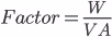
with any increase in volt-amperes without a corresponding increase in watts will lower the power factor. A lower power factor will affect facilities in two ways: Losses inside the facility will increase due to the higher level of current required to perform the work.
Utilities will charge a penalty if the power factor falls below a predetermined level. Both of these will increase utility bills.
Overheating of transformers is another issue associated with harmonic currents. Overheating shortens the life of the transformer. ANSI/IEEE Standard C57 states that a transformer can only be expected to carry its rated current if the current distortion is less than 5%. If the current distortion exceeds this value, then some amount of de-rating is required. The overheating is primarily due to the higher eddy-current losses inside the transformer than were anticipated by the designer. The overheating can be avoided by either de-rating the transformer or by specifying a “k-rated” transformer that is designed for the higher levels of eddy currents.
Another effect of harmonic currents on the power system is the overheating of neutral wires in wye-connected circuits due to the third harmonic and any multiples thereof that do not cancel in the neutral, as do other harmonic currents. The result is a large 180-Hz current in the neutral conductor—if there are significant non-linear loads connected to the wye source. Usually the higher multiples of the third harmonic are of small magnitude. The attended increase in the RMS value of the current, however, can cause excessive heating in the neutral wire. Currents as high as 200% of the phase conductors have been seen in the field. This large level of current can easily burn up the neutral creating an open neutral environment with very serious consequences.
Harmonic currents can distort the voltage waveform and cause harmonic voltages. Voltage distortion affects not only sensitive electronic loads but also electric motors and capacitor banks. In electric motors, negative sequence harmonics (i.e. 5th, 11th, 17th), are so called because their sequence (ABC or ACB) is opposite of the fundamental sequence, produce rotating magnetic fields. These fields rotate in the opposite direction of the fundamental magnetic field and could cause not only overheating but also mechanical oscillations in the motor-load system.
On facilities with capacitor banks, the reactance (impedance) decreases as the frequency increases. This causes the capacitor bank to act as a trap for higher harmonic currents from the surrounding utility system. The effect is an increase in current, in heating and an increase in dielectric stresses that could lead to capacitor bank failure.
Other Problems Caused by Harmonics:
Phase Shift Transformer is a distinct kind of transformer that has a special winding that changes the angular displacement between primary and secondary, also commonly called Harmonic Mitigating Transformers. Unlike a K-rated transformer, which only prevents the transformer and neutral conductor from overheating, a Phase-Shift Transformer uses a technique known as “phase shifting” to displace harmonic currents so that they cancel each other out. Harmonic treatment is provided entirely by electromagnetic flux cancellation; no filters, capacitors, or other such devices are used. It is important to remember that the harmonic currents still flow on the secondary windings.
It involves separating the electrical supply into two or more outputs, each output being phase shifted with respect to each other with an appropriate angle. The concept is to displace the harmonic current pairs in order to bring each other to a 180o phase shift thereby cancelling each other out.
So an angular displacement of 60o between two three-phase outputs will cancel the 3rd harmonic currents, an angular displacement of 30o between two three-phase outputs will cancel the 5th and 7th harmonic current pairs, and an angular displacement of 15o between two three-phase outputs will cancel the 11th and 13th harmonic current pairs.
For example, using a Phase Shift Transformer solely by itself (either 0o or 30o), can reduce the 3rd, 9th and 15th harmonic currents. When used in pair with both 0o and 30oPhase Shift Transformers, it can eliminate all 3rd, 5th, 7th, 9th, and 15th harmonic currents.
In summary, harmonics need to be controlled and should be reduced as much as possible—especially when they become a problem. A Phase Shift Transformer eliminates specific harmonics and attenuates the distortion to minimum values, providing protection against these electrical disturbances. Using Quality Transformer and Electronics' Phase Shift Transformers will solve the problems mentioned above ensuring that your power distribution systems are completely compatible with each other.
Quality Transformer and Electronics is your source for all your transformer needs. Our Engineering Team can assist you in specifying, designing, and manufacturing your needed transformers. We want to help you understand more about transformers and how we can assist in your selection of Phase Shift Transformers.
Since the widespread distribution of electricity has existed, so have transformers. In 1894, Sir John Fleming wrote a book on the transformer—the first on the subject in the English language (Grossner, 1967). While the technology of the transformer is older—and has lost much of its appeal—it is still extremely necessary for the proper functioning of nearly all electrical devices and equipment. While most know what a transformer does, few know how the transformer does it. Through induction and conduction, a transformer transforms one voltage to another voltage.
While the real-world transformer can have a number of parts needed for practical use, the ideal, theoretical transformer is comprised of just a few, non-moving parts. Broken down to its most basic form, the transformer is comprised of a core, commonly laminated steel, that will carry the magnetic flux which is a key component to the concept of the transformer, and the coil, commonly made of a conductor (i.e., copper or aluminum) and insulating materials (Tufquin or Nomex).
By mechanical design, the transformer core is comprised of a closed ferromagnetic core containing a hole through which magnet wire can be wound (see diagram)—think of it like a donut. This allows “both magnetic flux and current [to] travel a closed path and are linked with each other” (Grossner, 1967). This simple requirement allows a many variations within the construction in terms of size and shape of core and coil. “Yet, the size of any transformer may be conveniently characterized by means of its basic geometry, whatever its shape” (Grossner, 1967).
All cores have “a cross-sectional area, and so does the window or aperture associated with it, even though each core is constructed differently” (Grossner, 1967). Every core we encounter, no matter the type, has a magnetic path, defined by l. The coil, which passes around the core, through the window, and back around the leg, has an average length, or mean length of turn MLT.
There are three main core types to take note of when designing a transformer. They include laminations, toroid, and C core. Laminations consist of thin sheets of iron alloy, which are readily stamped or punched into different configurations that allow for easy assembly. These laminations are normally stacked one lamination next to the other, interleaved at the corners to create a solid piece of steel, commonly called a “Stacked Core”. The toroidal core is a donut-like core made of thin strips of iron alloy concentrically wound into its shape. The C core is comprised of two “C” shaped metal cores, essentially appearing as a toroid core cut in half.
The coil of the transformer is comprised of two components: conductors and insulators. Conductors (e.g., copper or aluminum foil or magnet wire, and Litz wire) are wound around the core. *Insulation is usually placed between the magnet wire and the core. In theoretical writing, often we describe the transformer as a single-phase transformer having two separate coils—one primary and one secondary coil. However, often times for practical purposes there is just one coil containing both primary and secondary windings in a single-phase unit. Although, with certain specialized transformers, coils may be wound any number of ways as is needed (Grossner, 1967).
“In practice the primary winding may be split, there may be more than one secondary winding, and any of these windings may consist of several layers of continuous magnet wire which has been wound either around a coil form or directly on the core” (Grossner, 1967). The wire is wound around a “leg” of the core helically, and is called a “winding”.
The transformer is one of the most relied upon and critical components of any electrical system. The transformer is comprised of a coil, or coils, placed appropriately so that the changing current from one coil—when hooked up to a power source—induces a magnetic field. This magnetic field excites the electrons in the second coil, inducing a voltage.
Now, the voltage induced in a coil is equal to the change of magnetic flux linkages N∅ with respect to time, otherwise known as Faraday’s Law. “Mathematically:
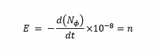
“where E is in volts, N is the number of turns, and ∅ is the flux in Maxwell’s or lines” (Grossner, 1967).
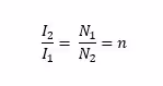
It is important to understand that the change in voltage from the primary winding (input winding) versus the secondary winding (output winding) is directly proportional to the number of turns in each winding.
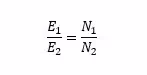
Here, the current is supplied by the power source to the primary coil while the current flows through the secondary coil and into the load. “In the ideal transformer, where there is perfect magnetic coupling and no loss of energy in the form of heat, the output power equals the input power” (Grossner, 1967), or:
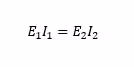
Essentially, this means to say that the power rating must be the same on both windings. “To maintain this relationship, the current ratio I2⁄I1=E1⁄E2 must be inversely proportional to the turn ratio” (Grossner, 1967):
We can see from these equations that the possibilities and combinations of turns ratios, voltages, and currents are virtually unlimited.“
The longevity of the transformer is undoubtedly due to the simplicity of its basic ingredients, copper, iron, and insulation, and also to the fact that is has no continuously moving parts” (Grossner, 1967). In fact, it is common to find transformers still running that were manufactured 20 or 30 years ago. The transformer is a reliable piece of electrical equipment to which the importance to the electrical utility industry is quite widely recognized.
Quality Transformer and Electronics designs and manufactures high quality transformers, and have been doing so since 1964 (over 50 years). We work with engineers and buyers to help specify the appropriate unit to fit their needs. Small companies or large companies, private or public, government or military, we have worked with, and delivered for, these companies repeatedly. Contact us for your next transformer needs.